 RushForth Tools for Revit: User Guide
Table of Contents (Click to Jump to Section)
RF AUTOMATOR: BASIC STEPS FROM START TO FINISH
RF AUTOMATOR: AUTOMATE PRINTING
RF AUTOMATOR: OPEN MODELS UNINTERRUPTED
RF AUTOMATOR: BIM360/ACC RVT AND NWC EXPORTS
RF AUTOMATOR: .BAT FILES CREATION AND USAGE
RF AUTOMATOR: PRESETS AND COLLECTIONS
PARAMETER TRANSFORMER: FILTER TAB
PARAMETER TRANSFORMER: MODIFY TAB
PARAMETER TRANSFORMER: EXCEL TAB
PARAMETER TRANSFORMER: TRANFORM TAB
PARAMETER LINKER: ORGANIZATIONAL OVERVIEW
PARAMETER LINKER: CREATING ELEMENT PAIRS
PARAMETER LINKER: MANAGING PARAMETER SETS
PARAMETER LINKER: MANAGING UPDATES AND SYNCHRONIZATION
PROJECT SETUP (VIEW AND SHEET CREATOR)
PROJECT SETUP: PROJECT SETUP TAB
PROJECT SETUP: CREATE SHEETS TAB
PROJECT SETUP: CREATE VIEWS TAB
PROJECT SETUP: DEPENDENT VIEWS TAB
PROJECT SETUP: MANAGE VIEWS AND VIEWPORTS TAB.
PROJECT SETUP: MANAGE SHEETS TAB
RAYTRACE ELEMENT COPY: WINDOWS
ELECTRICAL FIXTURE CIRCUIT TAGGER
The purpose of this document is to provide users with some basic instructions on how to make use of the included tools.
RF AUTOMATOR
The RF Automator allows to you initiate tasks from outside of Revit, and schedule recurring Revit tasks on multiple models. Clicking the RF Automator button in Revit will open the tool, but the tool can be run outside of Revit, so you may want to right click and pin the tool to your windows task bar the first time you run it.
Here are some of the things you may want to use the tool for:
· Automate tasks your engineers and designers are doing when they can’t afford to wait for production to help
· Automate opening large models off-hours so you don’t have to waste time waiting for the model to open at the beginning of your day
· Schedule weekly model downloads from ACC/BIM360 so you have a backup on your network
· Print sheets from your own model and linked models on demand or on a schedule
· Collect data from multiple models by accessing, opening, and performing any type of custom C# code on all your models
Important: When there are updates released to the tool, you will need to click the RF Automator button in Revit at least one time in one version of Revit for the tool to get the latest version and features.
Here is a quick example of how you could use the tool to export NWC or RVT files on a schedule. The basic steps are listed to show you an overview of the process, but if you would like more details on the individual steps or options, continue reading the sections below.
1. Open the RF Automator
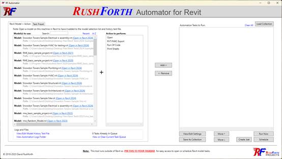
2. Select the model
3. Select the RVT/NWC Export action
4. Click Add
5. Set any options you want and click Confirm
6. Click the Schedule button and set the times you want
7. Read the important message thoroughly so you understand the windows scheduler options
8. If something doesn’t happen as expected, check the RF Automator logs to see if the task was successfully received and started by the tool. If it never got to the logs, then it could be an IT permissions issue with the windows task scheduler, and you can have IT check the windows task scheduler logs and the Windows event viewer for additional information.
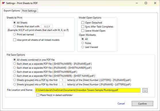
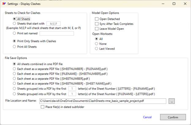
You can request Revit to print your model even without having Revit open. The tool will list the names of the models that you have opened on your machine so you can just select the model you wish to print. The print function only works on version Revit 2022 and later since that is the version Autodesk included a common PDF driver/exporter for the API to access.
Your options:
· Sheets to Print
o This section allows you to choose to print all sheets, or you can choose to only print sheets that start with certain letters. You can type as many letters as you need. Typing ‘AS’ in the box will only print sheets that start with ‘AS’. If you would also like to print sheets that start with ‘AG’, you can separate them with commas like ‘AS,AG’
o You can also type the name of a print set as defined in Revit. The tool runs outside of Revit, so you will need to remember the name of the print set to type it in.
o Note: in Revit 2023 and later, Autodesk enabled print sets to set custom print order. In Revit 2022, it will print alphabetically
o If you would like to quickly create a print set in Revit based on sheet names, or other parameters, there is a function in the Project Setup Tool, Manage Sheets tab that can help you do this.
o If you choose the “Also print all sheets of all linked models”, it will do exactly that. It will not filter which sheets to print based on the above filters, it will print ALL the linked sheets.
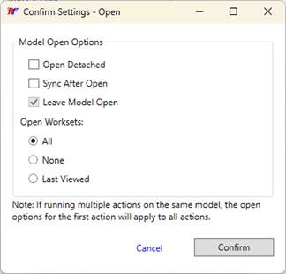
· Model Open Options
o These are the same in all the functions and are options for how to open the model. Most of the time you will want to leave these as the defaults unless you are wanting a different behavior.
o The Worksets option should stay at ‘All’ unless you understand why the other options exist when opening a Revit model.
· File Save Options
o This section is a huge time saver because it allows you to save the files in industry standard ways that the default Autodesk printing just doesn’t support.
o The “All sheets combined in one PDF file” will create one PDF per model. If you have selected to print linked sheets, there will be a PDF for each link.
o The ‘Each sheet as a separate PDF…” options give you various naming options for the individual PDFs.
o The “Sheets grouped into a PDF…” options allow you to group sheets by discipline or by sheet type. For example, if you wanted to print all “EP” sheets in a separate file from all “EL” sheets, you can specify to group by the first 2 letters of the sheet number.
o If you are scheduling recurring printing, the PDFs created each time will replace the existing PDFs in the folder unless you check the option to “Place file(s) in dated subfolder”. In that case, a new subfolder with the day’s date will be created each time the task is run.
o Selecting multiple models to print: What happens to the naming?
§ You can select multiple models to apply the Print Sheets action to. In that case, the options page will still show only one file location and name. When you click the confirm button, it will create a separate task for each model in the Automation Tasks to Run list. In each created task, the tool will automatically substitute the model name of each model for the model name shown in the selected name, so each model will be saved separately.
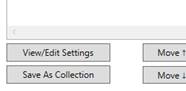
§ If you removed the model name from the name or you would like to do further customization for each of the tasks, you can click on each task in the Automation Tasks to Run list then click the View/Edit Settings button to assign a specific file name for each task.
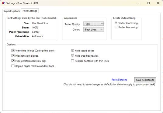
· Print Settings
o These are the same settings that are available inside the Revit print settings dialog. Refer to the Autodesk documentation for settings descriptions.
o This tool automatically uses the sheet size as specified in the Revit model for the PDF sheet size. It also locks the placement to Center to avoid documented glitches in the Autodesk print driver that can happen when using other placement options.
o You can modify the settings for your current task then just go back to the Export Options tab, or if you would like to save your changes to be your default any time you use the tool, you can click the “Save As Defaults” button.
In addition to automating and scheduling tasks, there are also things that this tool simplifies immediately. Instead of opening Revit first, then searching for your project, then maybe forgetting that the file was actually in a different version of Revit, then having to open that version and searching again… you can just open the RF Automator and click the blue link next to the model name to open it immediately.
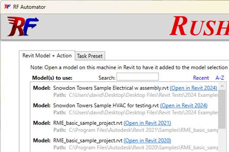
1. Ways this is faster than opening in Revit:
a. Instead of thinking about which version of Revit a project was saved in then having to browse through multiple BIM360 or ACC account hubs to find what you are looking for, just to remember that you actually are in the wrong version of Revit, you can easily just click to open any previously opened model and it automatically opens the correct version of Revit for the file.
b. The tool keeps track of all the models you have opened, so you can see all your recent files for all versions of Revit in one place. You can sort by recent or by project name, and you can also search for the project name.
i. You can also see a timestamped history of all the files you have opened in all versions 2020 and later. If you want to declutter the list and get rid of items from last month or last year, feel free to delete them from the history.
c. The tool suppresses all of the warnings when opening a file so it doesn’t pause when opening.
i. How many times did you start opening a file then started working on something else while it opened? You come back to the file 20 minutes later only to realize that it paused a minute into the process to ask you a pointless question.
ii. Suppressed messages will be included in the logs so you can still review them as needed, but they won't need to interrupt your workflow.
2. Open Settings
a. The settings are the same as the Autodesk open settings, so you can reference the Autodesk documentation for any questions on what they do.
3. Scheduling a model to open
a. You can schedule large models to open the next morning before you start work so they are ready for you when you start your day
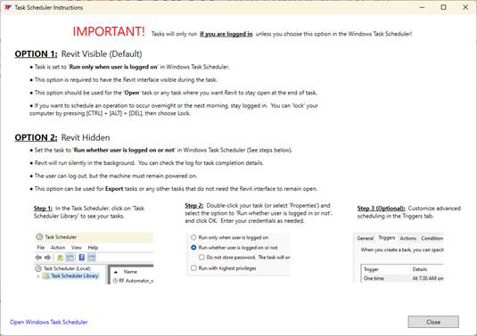
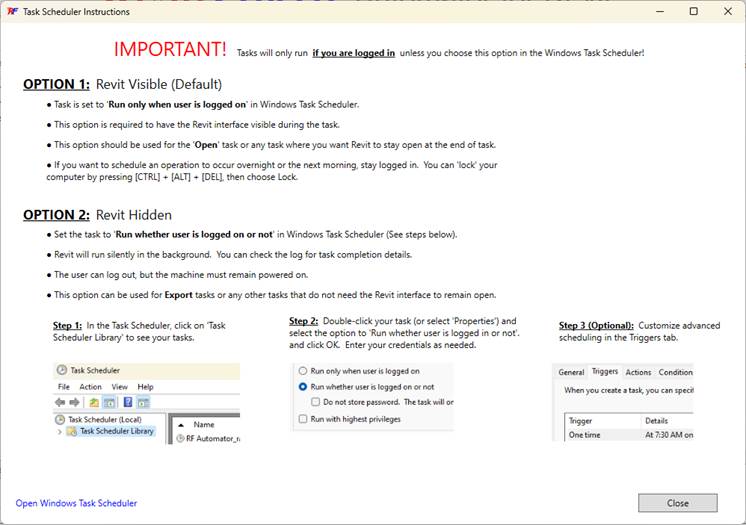
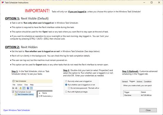
b. Don’t ignore the important note that appears when starting the Windows task scheduler from the tool.
i. Windows only allows a program’s interface to be visible if it is run during a logged on session. Otherwise, it runs in the background.
ii. What that means is that for you to be able to have Revit open while you are not there and then be able to view and use that Revit session, you will need to use the default option to only run when the user is logged on.
iii. If you want Revit to be open for you when you start work the next morning, you will need to stay logged in to Windows at the end of your day. You can still ‘Lock’ your machine, but you can’t be logged out entirely.
iv. Other tasks in this tool (like printing, exporting, etc.) can be run in the background without a user logged in, but because of the Windows Task Scheduler limitations, having access to the Revit interface for a model you want to open for you requires you to be logged into Windows.
For many years, people have been using the RVT/NWC export tool to export models to NWC or to create backups of cloud-hosted RVT models, but with the RF Automator tool you can do it across multiple models, and you can even schedule it for after hours or repeating at regular intervals.
There has been an increase in hosting Revit models in the cloud, but also an increase of companies losing access to their design models because they are hosted on someone else's hub or the employee with credentials no longer works there. Worse yet is that many companies aren't even aware of how many models they have lost access to. It is good practice to create a backup of cloud-hosted models to your own network server at every major project deliverable.
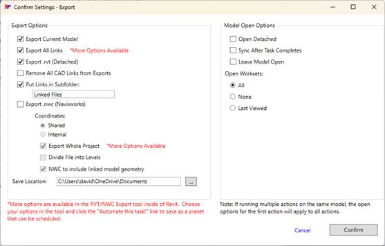
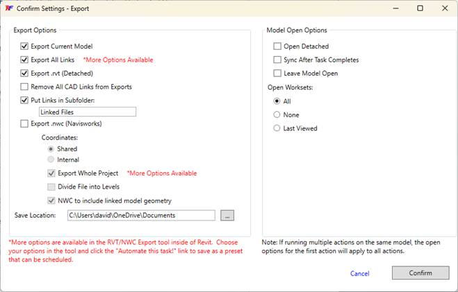
1. Export Settings
a. The export options are the same as the standard RVT/NWC exporter tool however there are two settings that are different.
i. When using the RF Automator, you get the option to export all or none of the links. If you create a preset in the actual tool, you can specify exactly which links to include.
ii. Similarly, when exporting to NWC, you can select individual views when creating a preset in the tool, but without a preset, the RF Automator defaults to export the whole project.
b. Note: The tool uses the actual most current BIM360/ACC design models and doesn't rely on a previously published model. That way you don’t have to mess with publish settings or rely on other consultants to publish their models in order to have the latest versions.
2. Model Open Options
a. Important: Avoid using the “Open Detached” option when automating exports. This will put the model in a new and never-been-saved state which can affect model property data and link locations. This could result in missing links or other information in exports.
3. Automating Exports
a. Read the .BAT file creation and scheduling sections below to see options on how to automate your exports.
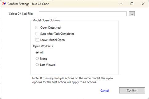
The Run C# Code tool allows you to type and run C# code without having to compile or set up Revit to run the compiled code. With the RF Automator, you can extend that capability to run custom code on any number of models and schedule it recurring as needed.
For example, you may want to:
· Collect custom data from your models and export that data to a .csv file for use outside of Revit
· Delete certain kinds of elements out of your models
· Select or modify elements based on criteria, formulas, parameter data
· Or anything else you can imagine and code
1. Example Code:
a. If you open the Run C# tool from the RF Tools toolbar, you can look at, edit, or copy from the example functions provided.
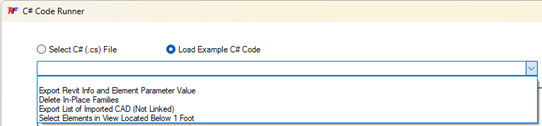
b. You can save your code to a .cs file that you can run again at any time and schedule in the RF Automator tool by just selecting the file you want to run.
c. You can run the code on multiple models by just selecting multiple models in the selection box when creating the task in the RF Automator.
2. Debugging
a. The tool will compile and run the code at the time it carries out the task.
b. You will want to make sure that the code works as expected before scheduling it to run in the RF Automator.
c. When running the code in the Run C# Code tool, it will notify you if there are compile errors so you can fix your code.
d. The editor in the Run C# Tool is just a text editor and is not a tool for debugging or suggesting code corrections. If you are just learning to code, start by changing simple lines of code, like changing the example to select elements below 3 feet instead of 1 foot to get familiar with modifying code. If you are interested in writing entirely new code and need some debug assistance, you should consider using a development environment such as Microsoft Visual Studio or other coding environment.
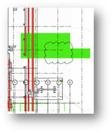
There are a number of clash detection tools available to review models, but most require you to learn a new software and perform a new workflow that in addition to your other design and review workflows. The Display Clashes tool allows designers to see clashes directly in the design software where they can find and fix them as part of their standard workflow. What the RF Automator adds, is the ability to automate the printing of colored sheets and clash reports across multiple models and on a scheduled basis.
As part of your standard design review, you can print your sheets with clashes visible so that senior reviewers can see both the design and potential construction issues without having to be in the design software. They can use the same PDF review workflow they are used to. Only the clashes that affect elements created on that sheet will be shown so you don’t have to sort through clashes that aren’t relevant or affected by the design currently being reviewed.
1. Options
a. The options available for this tool are very similar to the printing options since that is essentially what you are doing. Refer to the Automate Printing section above for additional details.
2. Results/Outputs
a. PDFs of sheets
i. The sheets printed using the options selected will automatically be printed in color so that the clashes will be shown as intended. If you would like to print with different color options, you can print manually from the Display Clashes tool directly.
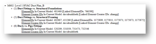
b. …-Report.html
i. In the same folder as the PDFs created, there will also be an html report automatically generated which will list each sheet and the clashes shown on that sheet, including the elementIDs and the username of the user that created the clashing elements. This will facilitate coordination between the designers associated with the clash.
Batch (.bat) files are simple scripts that Microsoft Windows uses to start an application and pass in parameters as needed. This can be a handy way to start a desired task at any moment rather than scheduling for a specific time. For example, you may want to print a set of PDFs for a model or backup a cloud model, but you don’t know when the designers will be done, so you want the option to just click start when you know they are ready.
1. Creating your .BAT file:
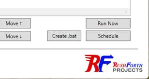
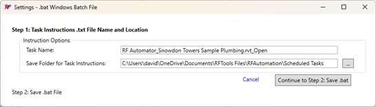
a. Once you have specified your tasks in the RF Automator, just click the button at the bottom to “Create .bat”
b. This will bring up Step 1, which is to pick a location to store the instructions file (see below for details)
c. After clicking “Continue…” you will be asked for a location to store the .bat file.
d. You can then double click the .bat file at any time to initiate the tasks.
2. Understanding the instruction file it uses
a. If you open the .bat file in a text editor, it will contain a path to the RF Automator.exe and a parameter after of a text file location that contains instructions.
b. The instructions file is actually the file that lists each task that Revit will perform. You can open that text file at any time to see what it contains. The formatting is the same as the other history and task files that are used by the tool which will contain a path to the model to open, the name of the function to perform, then a list of all of the options selected to be used for the task.
c. If you want to create a .bat file and make it available for other user users to start as well:
i. Just make sure that the instructions .txt file is in a location that others have access to (like a network folder instead of your personal profile documents folder).
ii. Then, as long as other users have the RF Automator installed and they have Autodesk access to the model being opened, they can just double click the .bat file to run the task as well. That way someone can cover for you if you are out of the office.
3. Notes on performing multiple tasks
a. The preferred method to run multiple operations at the same time on multiple models is to create a collection/list of tasks in a single RF Automator instruction file as opposed to creating multiple .bat files or combining the text of multiple .bat files into a single .bat file.
b. When the RF Automator runs an instruction file from the .bat file, it adds the tasks to the current queue and has Revit start on the list. If there are multiple versions of Revit needed, it will open each version of Revit which will only work on tasks that need that version. These tasks are done in parallel with the tasks being done by other versions of Revit. Within one version of Revit, the tasks are done sequentially in the order they are listed.
c. If you have multiple instruction files starting at the same time by executing multiple .bat files simultaneously, it could cause multiple instances of the same version of Revit to start and each would be working from the same exact list, so you could end up doing all of the same tasks multiple times and wasting time and processing power. Again, the preferred method is to initialize one larger automation list at a time, rather than multiple smaller lists to avoid duplication of efforts.
A preset allows you to select options in a specific tool then select that preset in the RF Automator and have it already set up to start the action. A collection is a list of tasks that will be performed on one or more models. This could be a combination of task types and presets.
1. Creating and Selecting Presets:
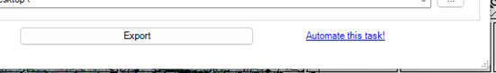
a. After selecting your options in tools like the RVT/NWC Export tool or the Run C# Code tool, you can click the “Automate this task!” link at the bottom of the tool to select a name for the preset.
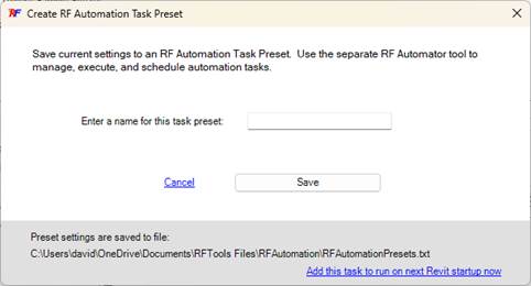
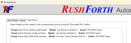
b. Then, in the RF Automator tool, you can use the Task Preset tab to select and use your preset
c. If you would like to be reminded or edit the options selected in a preset before running the preset, you can click the “View/Edit Settings” button after adding them to the Automation Tasks to Run list.
2. Collections
a. You can save a list of automation tasks as a collection by clicking the “Save As Collection” button.
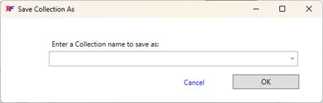
b. This allows you to reload that list at any time so you can modify or run those tasks again.
c. If you find yourself re-running many tasks lists frequently without editing them, you may consider saving it to a .bat file so you can just start the automation at any time.
The RF Automator allows you to schedule events to occur at specified times and intervals. It creates a Microsoft Windows scheduled event in the Windows task scheduler where you can continue to edit and maintain the task.
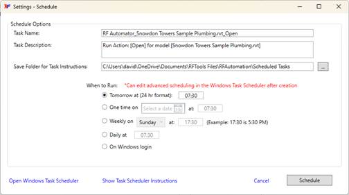
1. Creating and editing a scheduled task:
a. Once you have specified your tasks in the RF Automator, just click the button at the bottom to “Schedule”
b. This will bring up the schedule options

c. The Task Name and Task Description aren’t critical and are just used in the Windows Task Scheduler, so you can set those to anything you would like.
d. The save folder for task instructions isn’t important and can be left as default, but you can read additional details below in the section “Understanding the instruction file it uses”. If you would like to make some of the instruction files available to multiple users, you could consider saving them to a network location.
e. There are some basic scheduling options available in this tool, but there are even more options in the Windows Task Scheduler. Feel free to modify the schedule settings in the Windows Task Scheduler as you please.
f. You can come back directly to the Windows Task Scheduler at any time to run a task on demand, or to make edits to the schedule, or to delete the task.
2. Notes and cautions on scheduling multiple tasks for multiple models
a. The RF Automator Tool writes tasks to a text file on your computer. This text file is the same file used for all versions of Revit. When Revit opens, it reads the text file and puts all tasks that are for its version in a list to process. This means that you can have multiple versions of Revit running tasks at the same time in parallel, but it also means that you shouldn’t have multiple instances of the same version of Revit working on the list at the same time because they will be running the same tasks in the same order and just duplicating efforts.
b. For large scale automations, you could consider running automations on more than one machine to do efforts in parallel that would otherwise be done in series on a single computer.
1. Troubleshooting a scheduled task:
a. Most users shouldn’t have any issues getting tasks to run at their scheduled time, but there are a few things to be aware of.
b. Overview: There are four parts to the automation that must be working for the task to complete, and the RF Automator Logs can often help you determine where the issue may be. You can view the logs by clicking the “View Automation Logs Folder” link in the RF Automator Tool
i. Windows Task Scheduler: This is what starts the scheduled task, and you can tell if it is working if you see in your RF Automator log file “[SCHEDULED TASK STARTING] RFAutomator has been started from a scheduled task.” If you don’t see any log entry at the time your task is scheduled, then the issue is likely with IT permissions on your Windows Task Scheduler. See below for more details
ii. RF Automator: This part accepts the task, adds instructions to the automation queue that Revit uses when it starts, then tells Revit to start. If this is running correctly, you will see a log entry indicating that it is starting Revit: “[SCHEDULED TASK STARTING] RFAutomator is starting Revit 2022”
iii. Revit: Revit starts up and checks for any automation tasks in the queue that are for this version of Revit. You can tell if Revit started correctly if there is a log entry like “[Revit 2022: STARTING TASK]”. If the log stops at the previous entry and Revit never starts, then something is preventing Revit from starting. This could be that your Autodesk user account isn’t logged in to that version of Revit, or it could be that your Revit license is tied to a network resource and you aren’t connected to the network at that time. If you connect to a VPN for access to your license, then you may choose to remote into a machine that is always on the network to run the automations.
1. If Revit doesn’t start correctly, the queue will still contain the task to be run and Revit will see them the next time that it opens correctly.
iv. The requested tool: Once Revit opens, it will start the requested tool (PDF printing, clash reporting, C# code, etc.) which will then run with the settings selected. Once complete, it will log the task as complete in the log and remove it from the queue. If it does not complete successfully, it will remain in the queue and will be started again the next time that Revit is opened. When Revit opens, it will let you know that there is something in the queue and allow the user to choose whether to run the automation. You can also choose to clear the queue so it doesn’t ask again to start the next time Revit is opened.
c. First, don’t ignore the important note that appears when starting the Windows task scheduler from the tool.
i. Windows only allows a program’s interface to be visible if it is run during a logged on session. Otherwise, it runs in the background. This is important depending on which kind of task you are running.
ii. If you are opening a model to then work on it, you need to use the option of running when the user is logged on (see the section above on opening models)
iii. If you are printing, exporting, running code, etc. then you can use either option, including running when you are logged off.
c. Every time a task is received from the Windows Task Scheduler, the RF Automator will log the receipt as well as other actions performed.
d. If a task doesn’t complete as expected, check the RF Automator logs to see if the task was successfully received and started by the tool. If it never got to the logs, then it could be an IT permissions issue with the Windows Task Scheduler and you can check the windows task scheduler logs and the Windows event viewer for additional information.
i. 
ii. Check for any warnings at the scheduled time that may indicate that you need additional permissions to run the task. Send the details of the warning to your IT department
1. ![]()
e. If you get a warning in the Windows Task Scheduler when trying to select the option to Run whether user is logged on or not, then you will need to contact your IT and make sure that they have not disabled that permission.
![]()
f. What if I accidentally log off then a task that requires the user to be logged on doesn't run?
i. You can choose options in the task scheduler to either automatically run the next time you are logged in, or you can initiate the task to run any time you want by starting it manually in the task scheduler.
g. File Paths when logged out: It is important to note that if you have a task running when a user is not logged on, then you must use UNC pathing for any network files, including save paths for exports.
i. If you are using a mapped drive letter, like G:\ that maps a network path \\MyNetworkPAth\..., then many times, that drive mapping won’t exist until a user is logged on.
ii. Make sure that you use full network paths and not drive letters if you are running tasks while not logged on.
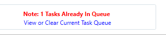
h. If a scheduled task does not complete (it was stopped, it errored out, etc.) it will remain in the Task Queue that Revit will use the next time it starts. If you add a different task to the Queue, it may be surprising to see it start a different task first. If you would like to clear or modify the queue at any time, you can click the “View or Clear Current Task Queue” link at the bottom left of the RF Automator tool. This is also where you will see a notification if there are already tasks in the queue waiting to get started. Tasks will start automatically the next time Revit opens (whether you open it manually or using the tool).
i. One known issue that can keep an export task from completing in the background is if a model is using Autodesk Desktop Connector to link .rvt files to the Autodesk Desktop Connector path instead of linking directly to the model in the cloud. In this case, Autodesk Desktop Connector can sometimes display warnings that the user must click in order to continue. These warnings are outside of the Autodesk Revit API control and Autodesk indicates that they are there because linking .rvt files using desktop connector paths is not supported and is known to cause project issues.
i. In this case, you should run export tasks while the user is logged on so that the user can click the warning messages that pop up. If this affects a large number of exports you do, reach out to support to discuss additional options for suppressing those messages automatically.
2. Understanding the instruction file it uses
a. If you open the scheduled task in the Windows Task Scheduler then look at the Actions tab, it will contain a path to the RF Automator.exe and a parameter after of a text file location that contains instructions (just like the .bat file mentioned above).
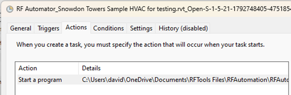
b. The instructions file is actually the file that lists each task that Revit will perform. You can open that text file at any time to see what it contains. The formatting is the same as the other history and task files that are used by the tool which will contain a path to the model to open, the name of the function to perform, then a list of all of the options selected to be used for the task.
3. Additional Tips and Troubleshooting
a. If you get permissions errors, like “Access Denied” or the “Permission Denied” then you need to contact your IT department to stop blocking the action you are performing. For example, you may get an access denied when the tool is trying to copy the RF Automator.exe file which could be caused by an IT policy of not allowing .exe files in your profile or certain locations. Your IT department can adjust the rule or create an exception for the certified digital signature used on the .exe. If your IT has group policies that block the use of the Windows Task Scheduler, one known workaround is for the IT department to use tools like CyberArk to manage access to specific users.
b. There are several logs and text files that can be helpful in viewing task or model history and for seeing what is currently in the task queue. Feel free to delete these files or edit the contents. For example, you may want to remove a model from your open history, or you may want to see which settings were used in a previous automation.
c. TIP: You can copy tasks and presets between text files for various reasons:
i. You may want to add a recently run task to an existing instruction file, preset, or collection.
ii. You may want to add a recently run task to an existing preset so you can use the View/Edit Settings button in the tool to view or edit all the settings that were used for that automation. You can also copy text from another user’s file into your own files for the same reasons.
iii. You may want to copy a previously run task or a preset into the current queue file (RFAutomationTaskList.txt) then open Revit to have it immediately run that action.

PARAMETER TRANSFORMER
The Parameter Transformer is used for advanced
filtering and modifying of elements including synchronizing data with Excel.
In the provided examples that demonstrate uses of the tool, the reader should focus
more on the process being performed than the actual element types being
modified. The same processes can apply to any number of element types. 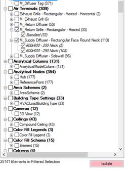
Revit’s selection filtering is limited to category types and does not allow you to find elements by family name, type, parameter values, etc. The Parameter Transformer allows filtering by all of these and allows you to combine filters on top of other filters
4. Filter selection by Family and Type:
a. The selected items box at the right can allow you to quickly select filter your Revit selection to only your desired families and types.
b. EXAMPLE: Filter your selection for only a couple types of Air Terminals:
i. In Revit, select a region of the view that has elements you want to filter for (or you can filter all elements in the project).
ii. Open the Parameter Transformer and you will see a list of the families that you have selected. Notice the number of elements selected is noted at the bottom of the list and for each family and type.
iii. Now, select the Air Terminal families and types in the list and click the ‘Isolate’ Button
iv. This narrows the list and also changes the physical selection in Revit to match the filtered list.
v. If you exit the Parameter Transformer, you will see that only the family types you filtered for are in the current selection. You may now edit them as needed (e.g. change the workset of all elements together).
5. Filter the entire project for categories and parameter values
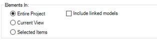
a. At any time you can choose to search all elements in the current view or the entire project by selecting the appropriate option. You can also choose to include linked elements. Note: Linked elements can be used for exporting data, but cannot be selected or modified in the current model.
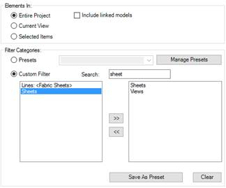
b. EXAMPLE: Find all views and sheets in the project whose sheet name contains “Level 1” and whose sheet number contains “P”
i. Open the Parameter Transformer and select ‘Entire Project’ then do a custom filter search for ‘views’ then ‘sheets’ and add them to your category list
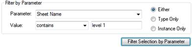
ii. Now filter for parameter ‘Sheet Name’ contains ‘level 1’. This will show all sheets with this text in their name and all views that are placed on sheets with this text in their sheet name.
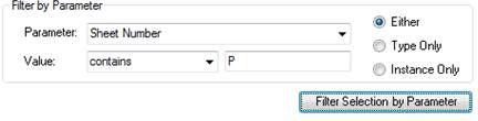
iii. Next, fill out the parameter filter boxes again, but this time for ‘Sheet Number’ contains ‘P’. [Note that after the previous filter, the element selection changed from ‘Entire Project’ to ‘Selected Items’. The next filter will build on the previous filter. That way you can add any number of filter combinations you want. You can reset the filtered set by resetting the top filter to ‘Entire Project’.]
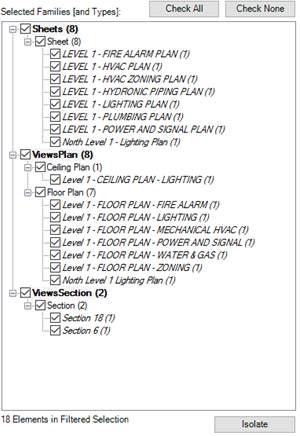
iv. You have now filtered your selection to only those views and sheets matching both the criteria. You can now use that selection in Revit or in other parts of the Parameter Transformer.
c. Notes:
i. Can search for blanks and ‘-1’ for none, 1 for true, 0 for false
ii. Can use greater than for numbers and text
iii. Other useful filters
1. Find all elements on wrong workset
2. Find all elements with host ‘not associated’
The MODIFY tab is for quickly setting the parameter value of all selected elements to the same value (including ‘find and replace’ in parameter values) or for automatically numbering parameter values for elements.
NOTE THAT ALMOST ANYTHING DONE IN THIS TAB CAN ALSO BE ACCOMPLISHED USING THE EXCEL TAB. One exception is the Delete button that can help purge selected categories out of a model.
1. Modify parameter values of multiple families at once
a. One advantage that this has is that the parameters being modified do not have to be the same shared parameter (like they do when editing multiple elements in Revit) and you can even choose to edit all parameters that CONTAIN the specified text (like all parameters containing ‘Level’ will affect ‘Level’, ‘Scheduled Level’, ‘Base Level’, etc.
b. EXAMPLE: Change the length of multiple lighting fixture families to the same value
i. Select multiple lighting fixtures in Revit then open the Parameter Transformer
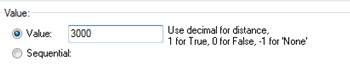
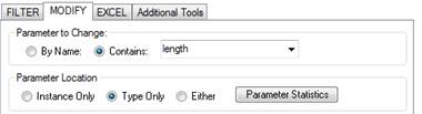
ii. Activate the MODIFY tab and choose or type in the parameter name you wish to modify. In the Autodesk sample project I am using, the parameter is called ‘Light Casing Length’ so I will just select ‘contains’ ‘length’. You can also choose whether to affect matching type or instance parameters or both.
iii. Then I just specify the value ‘3000’ and click ‘Modify Parameters’ (this Autodesk sample is metric and the units are millimeters)
iv. All of the selected types are modified at the same time.
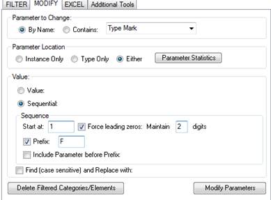
2. Automatic numbering of instances or types
a. The automatic numbering allows you to choose a starting sequential value, force leading zeros and even add text or parameter values as a prefix.
b. EXAMPLE: Renumber all lighting fixtures Type Mark values
i. Open the Parameter Transformer and select ‘Entire Project’
ii. Filter for all lighting fixtures by either selecting a preset, or adding the category to the category list.
iii. This will add all lighting fixtures in the project to our selection set.
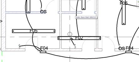
iv. In the MODIFY tab of the Parameter Transformer, and select ‘Type Mark’ for the parameter and set the value to sequential, starting at 1, maintaining 2 digits, and with prefix ‘F’ and click ‘Modify Parameters’
v. You will see on your schedules and floor plans that the values and tags have all been updated (see screenshot below of the Autodesk example project we were editing)
3. Find and Replace text in parameter values
a. Find and replace can be a quick way to fix spelling mistakes or modify sheet and view names (especially dependent views)
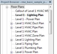
b. EXAMPLE: Find and replace Level 1 with Floor 01 in all view names
i. Open the Parameter Transformer, click ‘Entire Project’ and use the preset to select all views in the project.
ii. In the modify tab, select ‘View Name’ as the parameter, then type the text you want to find in the Value box. In my case, I will search for ‘Level 1’
iii. Check the Find and replace check box and type the new replacement text in the box (‘Floor 01’).
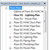
iv. Click ‘Modify Parameters’ and you will see the replacements made throughout the project.
 becomes
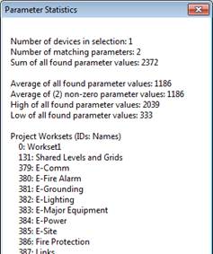
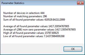
4. Parameter Statistics
a. This button allows you to return statistical information about the values for the selected parameter. Values computed include Sum, Average, High, and Low.
b. EXAMPLE: Find the total length of a run of ductwork
i. Use the TAB key on the keyboard to help select a run of ductwork on the drawings (same can apply to pipes, conduits, walls, etc.)
ii. Open the Parameter Transformer and go to the MODIFY tab
iii. Select ‘Length’ for the parameter and click the ‘Parameter Statistics’ button
c. EXAMPLE: Return WorksetIDs for all worksets in the project
i. Some external applications including previous versions of Navisworks have access to WorksetIDs but not the workset names. This can be a quick way to lookup those IDs in a project
ii. In a workshared model, open the Parameter Transformer and with any element in the selection set, choose ‘Workset’ as the parameter and click the ‘Parameter Statistics’ button
5. Delete/Purge
a. You can remove all selected elements or categories from a model by using this Delete button
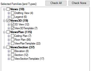
b. EXAMPLE: Purge all 3D views from the model
i. In the Parameter Transformer, select ‘Entire Project’ then use the “Views” preset to filter for all views in the project
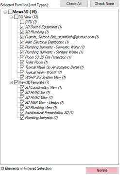
ii. “Check None” then check the 3D Views category and click ‘Isolate’
iii. I usually select everything but the Default 3D view (mostly because I use the Default 3D view for raytrace functions on linked models
iv. Then go to the MODIFY tab
v. Click the button ‘Delete Filtered Categories/Elements’ and they are removed from the project.
This is by far the most popular tab as it allows you to extend your editing, sorting, filtering, and calculation capabilities with all the built in functions of Microsoft Excel. Revit element data can be modified in Excel then imported back into the Revit database. The tool also allows bringing in data and calculations from outside sources into the Revit database.
One item to note about this Excel tool is that it does not gray-out columns in Excel or prevent you from attempting to edit data that is read-only in Revit. That is because this program was designed for maximum flexibility and exports to columns based on parameter name and not unique ID. This was done on purpose to allow you to edit all parameters called ‘Length’, ‘Voltage’, ‘Material’, etc. in a matching column whether or not they came from the same shared parameter file, are type vs instance parameters, or family vs project parameters. You will be notified if any changes were unsuccessful, and you can always re-export to another excel file to compare before and after values of the Revit database.
Understanding the Excel File used:
For the most part, you will not be required to understand how the program uses the Excel file, but it is always good to know. The tool creates its own Excel file and expects columns and rows to be in certain locations for proper operation. Here are some of the specific features/requirements of that excel file:
· Row 5 is used for Parameter Names
o Column A and Column B of Row 5 are the parameters used for selecting elements to modify. Elements that have the value listed for the parameter given will be selected for modifying the parameters listed in the rest of the row. The default matching criteria is ElementID so an identical match can be made. Column B is automatically used when exporting Data from linked models to identify the model the element came from.
o Columns C and higher are used by the program for listing the parameter names to be exported/imported. Exporting/importing stops when the program encounters a blank cell reading across the row starting at column C.
· Row 6 contains the headers for the table of values. It allows you to sort and filter the data to facilitate working with the data in Excel. The column names are automatically set to equal the parameter names for convenience. Yes, it would be possible to combine these two rows in the program, but column headers cannot be blank and there could be potentially other conflicts, so the choice was made to have the parameter values listed above the actual table.
· The rest of the rows below 6 are used by the program to export and import the selected data
1. Exporting, Modifying, and Importing selected parameters
a. Data from selected elements can be exported to Excel where it can be modified and brought back into Revit
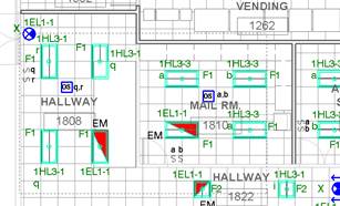
b. EXAMPLE: Modify lighting fixtures length, rotation, and IsWorkplaneFlipped property using Excel
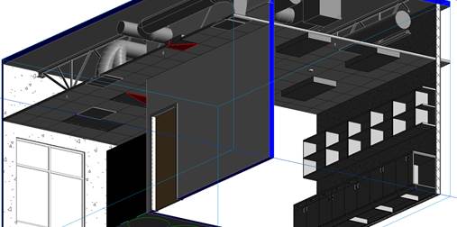
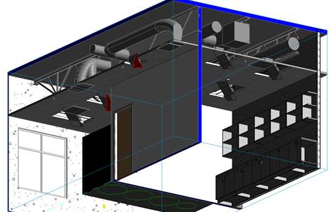
i. On a floor plan I am reviewing some of the lighting fixtures and want to make some changes. Before I begin, I will use the 3D sections tool to look at this selected area in 3D so I can verify that all the lights are recessed correctly.
ii. Looking from the bottom right up toward the ceiling:
iii. All of the lights should be recessed, but the fixtures on the right are not placed properly. I will also change some of the other parameters for demonstration purposes.
iv. Select the lighting fixture in the area in your plan or 3D view
v. Open the Parameter Transformer and narrow your selection by selecting only the families you wish to modify and click ‘Isolate\]
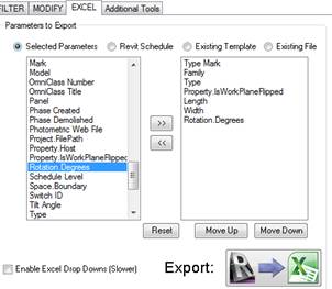
vi. Then go to the EXCEL tab and select the parameters you want to export (I am choosing ‘Type Mark’, ‘Family’, ‘Type’, ‘Property.IsWorkPlaneFlipped’, ‘Length’, ‘Width’, and ‘Rotation.Degrees’
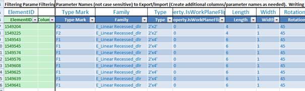
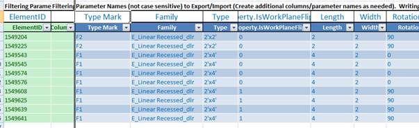
vii. Click the Export button to see the data in Excel.
viii. In excel, I notice that the fixtures on the wrong side of the ceiling have their Porperty.IsWorkPlaneFlipped value set as ‘1’ (True). I set these all to 0 then make changes to the length width and rotation.
ix. Save the worksheet then in the Parameter Transformer, click the Import button. You can choose the file names to export to and import from, or you can just use the default names if you don’t wish to store it for later.
x. In Revit, we can see that all of the parameters were modified successfully. Of course, the rotation and size of the fixtures looks odd because of the random values I chose, but you can see that the fixtures are now recessed properly and they are using the rotation and size values I changed.
2. Transfer data into Revit elements from external sources or calculations
a. EXAMPLE: Transfer space data out to Excel for use in external application calculations. Then import external calculation results back into Revit
i. Open the Parameter Transformer and use the preset to select all spaces in the project.
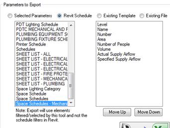
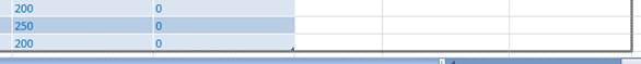
ii. In the EXCEL tab, I will select the ‘Revit Schedule’ option which allows me to pick from existing schedules in the project. My example schedule has parameters ‘Level’, ‘Name’, ‘Number’, ‘Area’, ‘Number of People’, ‘Volume’, ‘Actual Supply Airflow’, and ‘Specified Supply Airflow’
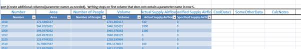
iii. When I click the export button this time, I am going to specify a new name for the file so that I can save it for later without overwriting custom calculations I will create in it.
iv. Now, let’s assume that you have an external application, spreadsheet, or other tool that runs calculations outside of Revit that may or may not use your output data, but it returns data to you in some sort of report that can be read by Excel (text, csv, xml, xls, … etc.)
v. THE QUICK WAY: As long as you have the same number of outputs as inputs and you can order them in the same way (meaning space 1 being copied to lines up with space 1 in the results), you can just copy and paste from one file to the other and import the results back in.
vi. THE MORE PERMANENT UPDATER WAY: Let’s assume that your calculation results may be in a different order or that spaces or calculations may exist in one list but not the other. We will use a simple Excel Vlookup formula to map the results to the correct line.
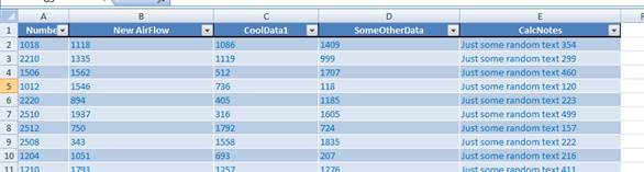
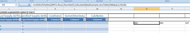
vii. For this example let’s assume that the results give you 4 values that you want to import back to Revit, but only one of the parameters currently exists to store the data. No problem. We will use a separate spreadsheet to represent the output of an imaginary calculation with outputs ‘Number’, ‘New Airflow’, ‘CoolData1’, ‘SomeOtherData’, and ‘CalcNotes’
viii. In our original excel file, I want to retrieve the New Airflow and other values if the ‘Number’ in the calculation output matches the ‘Number’ in my space schedule (of course there could be any number of ways you would like to map the entities to each other)
ix. I will start by copying the new parameter names into Row 5 of the Parameter Transformer Excel sheet so I will have a place to store the data
x. While not required, I could also extend my excel table to include these columns by dragging the bottom right corner of the table over to include the columns. This can help if using the headers to sort or filter.
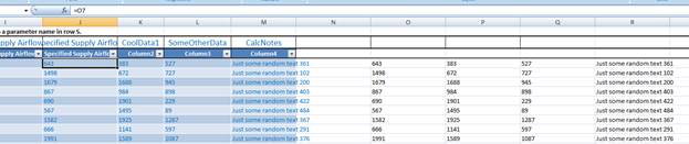
xi. Next, I will use VLOOKUP formulas to lookup the data from the other file. I actually start off to the right of my data table in cell O7 and start typing in ‘VLOOKUP(‘ then Excel starts prompting me to select the values to look up and the source for the table to look up in. In the end, my formula looks like this ‘=VLOOKUP(Table1[[#This Row],[Number]],CalculatedDataExample.xlsx!Table1[#Data],2,FALSE)’
xii. I copy this formula to the next three cells, except I change the end to ‘3, FALSE)’, ‘4, FALSE)’, and ‘5, FALSE)’ so that I return data from the correct column of the other sheet.
xiii. Now I set columns J, K, L, M from my table to equal the calculated fields off to the right. I also copy the formulas down to the end of the table to fill out the entire table. The reason why I typed the VLOOKUP formulas outside of the data table is to prevent them from being overwritten the next time you export. That way, the next time you want to do this process, it is as simple as exporting (using the ‘Existing File’ option), resetting columns J, K, L, M to be equal to the lookup values at the right of the table which will still be linked to the output of your calculations, then importing the changes.
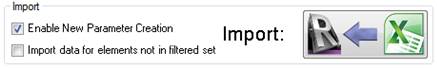
xiv. When importing data into parameters that don’t exist yet, you just have to check the option ‘Enable New Parameter Creation’
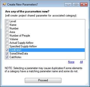
xv. This will give you a dialog that lets you choose which parameter to create during the import if they don’t exist. Note: You can also have columns in your Excel file that you use just for temporary calculations and may leave those unchecked. They will be skipped if they don’t exist for the elements.
xvi. When you proceed, all of your calculated data, including your new parameter data will be available in your project.
xvii. Note on creating new parameters for “data dumping”
1. This is a way to painlessly create project shared parameters that enable you to store, schedule, or export your new data. This method creates Instance, Text Parameters for maximum flexibility. If you would like to create standardized parameters of different types, export shared parameters, or create templates for use in other projects, refer to Parameter Scheduler tool.
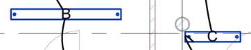
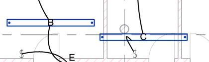
b. EXAMPLE: Transfer parameter data from one element type to another: material ‘Mark’ value to wall part ‘Mark’ value that use those materials
i. This can be accomplished the same way as described in the previous example.
ii. Export materials in the project including the ‘Type’, and ‘Mark’. Save that Excel file for reference.
iii. Filter the project by doing a custom search for the category ‘Parts’
iv. Export the Parts including parameters ‘Material’ and ‘Mark’
v. Now do a VLOOKUP formula as described above, matching the material name, to copy the appropriate Mark data from a matching material
vi. Note: This same method can be used to transfer data between equipment families and diagram families used to represent those elements. In some cases where the two elements have matching parameter names, they can easily be exported on the same spreadsheet and copied directly or through formula.
c. EXAMPLE: Transfer lighting fixture manufacturer and model information from linked architectural model to MEP model
i. In the MEP model, use the FILTER tab to select all lighting fixtures in the project and check the box to include elements in linked model. You can filter for only specific families and types as desired.
ii. In the EXCEL tab, select parameters to export (‘Type Mark’, ‘Family’, Type’, ‘Manufacturer’, ‘Model’)
iii. In Excel, copy and paste the values from the architectural elements to the MEP elements as desired then save the workbook.
iv. Use the Parameter Transformer to import the MEP element data back into Revit.
3. Importing data for elements not in filtered set
a. The default setting of the Parameter Transformer is to only affect elements that have been filtered in the Parameter Transformer interface (those families that show up in the selected items box at the right). This is convenient for importing and exporting only specific elements you want to modify. However, there are also powerful reasons to ignore the current filters.
b. Importing data for elements not in filtered set means that it will affect every element listed in the Excel file. This allows editing to be done separately in Excel by others and brought back in by the Revit user. It also allows users to make modifications to linked model data then bring the changed data back into the linked model later.
c. EXAMPLE: Contractor wants to modify the ‘Assembly Code’ and ‘Model’ parameters of the Structural elements in a linked model.
i. Contractor exports desired elements and selects ‘Include linked models’ to include elements from a structural linked model.
ii. Contractor edits the desired parameters in Excel, but the contractor cannot import the changed data through the linked model directly.
iii. He can open the structural model directly then import, or, he can send the Excel file to the structural engineer and request that the structural engineer import the changes into the model. That way the engineer can review the changes, and the changes will be included in the next structural model that the engineer shares with the contractor.
iv. The structural engineer could open their model and open the Parameter Transformer (with or without anything selected)
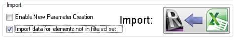
v. On the EXCEL tab, check the ‘Import data for elements not in filtered set’ then import
vi. The import will know which elements belong to the structural model as long as the filename of the structural central model matches the filename of the structural central model that the contractor used when exporting.
4. Placing existing views onto existing sheets and controlling viewport placement
a. If you specify “Sheet Number” for a ‘View’ (in the Parameter Transformer or Excel), it will create a ‘viewport’ and place it on the sheet in a default location.
b. You can also specify viewport locations on sheets in the Parameter Transformer/Excel to automatically line up all the views on all the sheets
i. To move ‘viewports’ that are already on a sheet, you need to select ‘viewports’ in the project filter and not ‘views’. Then you will have access to modify the location.x and location.y on the sheets. It is best to place one where you want it, then copy its location values to all the others you want to set.
c. Example: Place Existing Views onto sheets and control viewport placement
i. For this example, I will assume sheets and views are existing. You can use the Project Setup (View and Sheet Creator) to quickly create views and/or sheets if needed. The Project Setup tool also has tools to place existing views on sheets and control viewport placement.
ii. Use the Parameter Transformer to place existing views onto existing sheets
1. Filter for all views in the project, and export parameters to Excel (‘View Name’, ‘Sheet Number’)
2. In Excel, fill in the sheet number where you would like the view to be placed.
3. Import the saved Excel file using the Parameter Transformer to have it create a viewport for the view in a default location on the specified sheet. (Note: This process can take a while for a large number of views. You may want to practice on a small number first)
iii. Use the Parameter Transformer to adjust or match existing viewport placement on sheets
1. It is usually best to place one viewport at the desired location in one Revit sheet so you can copy the location values to all other viewports
2. In the Parameter Transformer FILTER tab, use the custom filter to include “Viewports” for the entire project (not views)
3. In the Excel tab, export parameters ‘Sheet Number’, ‘Sheet Name’, ‘View Name’, ‘Location.X’, and ‘Location.Y’ (this is another process that can take a while on a large number of viewports, try on a small set first)
4. In Excel, find a viewport that is at the desired location on the sheet and copy the X and Y locations to all the other views you would like to place at the same position
5. Import the saved excel file back in to see the modified viewport locations (note that the viewport x and y values are in feet [or possibly your project’s units] and based on the lower left corner of the sheet)
5. Other quick examples of possible uses:
a. Align vertical position of all selected tags
i. Use the Location.y values for tags to align or move them
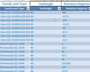
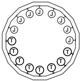
b. Rotate text in element symbols to all be upright
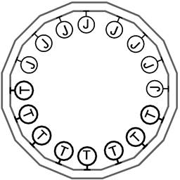
i. This example will look at a Thermostat and J-Box family that have a parameter built in them to control the text rotation. The parameter can manually be set to any rotation angle, but you can also export the elements’ rotation on sheet and automatically fix the angle for all elements in the project at once.
ii. 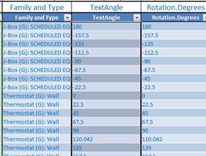
iii. Export the families’ ‘Text Angle’ parameter (assuming you have this set up in your family) and the ‘Rotation.Degrees’ property then set them equal in Excel.
Becomes:
iv. Save and import the Excel file to see:

c. Sheet list revision parameters
i. In Excel, Type new parameter names into row 5 such as ‘DELTA 3 2013-08-16’
ii. Fill out the column with values for the desired sheets. I use a bullet character that can be copied and pasted from the windows character map or you can use X’s or another character.
iii. When importing check the option ‘Enable New Parameter Creation’ to create the new revision columns and import the data. The new columns are now available for use in Revit sheet lists.
d. Create a filter parameter for selecting all even circuits on an electrical panel
i. You could use a new Excel column in your export to create a new parameter like ‘MyFilterParameter’. For this circuits example, I will use the Excel formula ‘=IF(MOD(RIGHT(Table1[[#This Row],[Circuit Number]],1),2)=0,1,0)’
ii. This formula sets the value of this new parameter to 1 if the circuit number is even and zero if the circuit number is odd.
iii. I can then import the results into Revit checking the option ‘Enable New Parameter Creation’ to create the new filter parameter.
iv. I can now use simple filters in the Parameter Transformer to find these circuits (filter for MyFilterParameter equals 1).
v. This may be helpful in conjunction with the Circuits Move tool that can move all these circuits onto another selected panel.
vi. The point to remember here is that you can use complicated Excel calculations to generate simple filters that can be used later for selecting and modifying elements.
e. Export X, Y, and Z coordinates of equipment and columns to find closest column using Excel formulas
f. Control parameters (such as stamp visibility, key plan selection, etc) for all title blocks for sheets whose number starts with M.
g. Change visual style of all publish views to hidden line.
h. Set scope boxes of all filtered views.
i. Find and replace text in electrical circuit names.
j. Changing types or renaming types for elements
i. You can change the ‘Type’ value in Excel.
ii. If the new type value already exists in the element’s family, the element will be changed to that type.
iii. If the new type value does not exist in the element’s family, it will rename the existing type to the new type name. All elements of the existing type will have a new type name.
k. Find all elements below the ceiling or above the ceiling
i. Use ‘Elevation’ or other parameters and use the less than and greater than filters to set the range
l. Set materials for elements.
m. Transfer data between spaces and rooms using the Excel Vlookup methods described in this guide.
6. Notes
a. If editing a type parameter and multiple elements are listed, be sure that all listed elements of the same type have the same value shown. Otherwise, the last value written will affect all elements of the type.
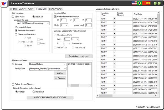
The transform tab displays the location information of all elements that you have selected or filtered and allows you to create other elements based on that information.
For example, you could perform tasks like:
· “For every desk in the linked model, create a floor receptacle at the nearest floor”
· “Convert this duct placeholder into a cable tray, wall, conduit, or any other line based element”
· “Using this conduit or pipe path, create a pipe hanger every 10’ along the path”
· “For every selected power duplex receptacle, create a data jack 6” to the right”
· “For every CAD lighting fixture block in the imported CAD file, convert those imported elements to Revit lighting fixtures”
· Etc.
1. Understanding the options
a. The locations listed at the right will show the locations of the elements that you have selected in Revit, or the elements that you have filtered in the Filter tab of the Parameter Transformer. If they are linear or curved elements, they will contain information about those lines, otherwise, it will be a point (x,y,z)
b. Get Locations
i. Same Place
1. For point sources, this will set the creation location to be at the same location. You can specify offsets to this location in the Location Offset section.
2. For linear elements, if you are creating a linear element, it will use the same path. If you are creating point location elements, then it will create copies of that element along the path and/or at the path ends, depending on your selections in the section “Generate Locations for Paths/Perimeter”
ii. Ray Cast
1. Geometry to Use
a. This is the model it will use for finding surface locations to host to
2. Perimeter Placement
a. This method only works when the source element you are using for locations is either a space or a room. It then defines the path of placement as being around the room and uses the options in the section “Generate Locations for Paths/Perimeter” for determining spacing of elements created.
3. Directional Placement
a. This will use the point location then the selected vector directions to place elements at the nearest wall in that direction.
c. Location Offset
i. These options allow you to set the offsets from the original locations for the new elements being created
d. Generate Locations for Paths/Perimeter
i. These options don’t affect anything unless the source element is a linear element, or you are using the perimeter ray cast options. For standard point location sources, the values of these settings will not make a difference.
e. Recalculate locations
i. Any time a change to options of offsets is made that will affect the final locations of the elements to be created, this button will change color indicating that you will need to apply those changes to the shown locations at the right.
2. Creating Elements
a. You can create one or more elements at the selected locations by selecting the category, family, and type of the family to be created.
b. Delete Source Elements
i. This option will replace the source elements with the new ones. For example, if you are converting pipes to ducts, or converting CAD lighting fixtures to Revit lighting fixtures, you may want to use this option. This option will not delete source elements if the source elements are in a linked Revit model.
c. Default Orientation for Face Based
i. The tool will try to match the orientation of the source elements when it is known, but if the elements are from CAD or there is not a known orientation, it will use this selection as the default.
ii. If you are placing elements on a floor or ceiling, choose horizontal. If you are placing elements on walls, choose vertical.
d. Hosting notes
i. This tool will attempt to host elements to walls, ceilings, etc. when the host is in the current model. When the host is in a linked model, this tool will place the elements at the correct location, but they will not have an actual host. This will not affect the usability or 3D accuracy of the model.
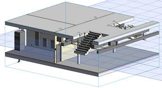
3D SECTIONS
The 3D Sections tool will quickly let you view areas of your plans in 3D. The tool turns on all model categories and worksets so that you see everything that exists in the area selected. This can be very helpful for coordinating the work or multiple disciplines or just for seeing what is going on in a particular area.

DRAW BOX: This option allows you to drag a box around an area in your plan view and see that area in 3D. It uses the view range of the current view for determining the upper and lower bounds of the 3D section box.
DRAR BOX (SHOW CUT PLANE): This works the same as the draw box mode, but it shows a plane representing the cut plane location of the current view. This is very helpful when troubleshooting view range issues so you can tell exactly which elements are above and below the cut plane.
SELECTED ITEMS: This will create a 3D view directly around the selected item(s). The bounds of the 3D section view are the maximum and minimum bounds of all of the selected items.
CURRENT LEVEL: The X and Y bounds are set by all objects in the view then adding a buffer to include the whole visible project. The lower bound of the view depth is the current level of the view and the upper bound of the view depth is the level above – 6” or 11’ 6” if there is no level above. The 6” below level above was done to avoid seeing the floor of the level above. This helps you see the floor plan of the current level with just a single click.
CURRENT LEVEL CEILING: 7’ 6” above the current level to the level above – 6”. The purpose of this option is to be able to quickly do ceiling coordination. The purpose of the 6” below the level above is to avoid seeing the floor of the level above so that you can have a clear view of the ceiling space.
ALL LEVELS: The X and Y bounds are set by all objects in the view then adding a buffer to include the whole visible project. The lower bound of the view depth is the current level of the view and the upper bound of the view depth is the level above. There are no offsets to the view depth applied so that if you are creating export views to programs such as NavisWorks, it will export every level and there will not be any gaps between.
PARAMETER SCHEDULER
The Parameter Scheduler allows you to easily make Revit families compatible with schedules by adding saved lists of shared parameters to them. It also allows you to organize and share shared parameters between projects, families, and teams.
Background:
Shared parameters are a very important part of how the Revit database functions. In order for elements to have their parameters visible on a schedule with other elements, the families they come from must be using the same shared parameters from the same source shared parameters file. This allows Revit to verify that they accept the same type of data and can be modified and scheduled the same way. Even if parameters have the same name, they can’t be scheduled together if they aren’t from the same source. Also, if you create a family with parameters as family parameters instead of shared parameters, then you cannot use the information stored in them in Revit schedules or tags. Without the Parameter Scheduler, correcting these issues would be a very time intensive exercise.
1. Making content compatible with your standard schedules:
a. If you have custom schedules that use any parameters other than the built-in Revit parameters, then any new content, or content acquired from a third party source (manufacturers, internet, etc.), will not be able to schedule this information until you add the original shared parameter to the family or project.
b. Using the Parameter Scheduler, it is as easy as selecting which preset schedule you want the Revit family to be compatible with.
c. EXAMPLE: Make a manufacturer’s lighting fixture family compatible with your schedules:
i. After you have downloaded the .rfa family file from the manufacturer, open the family in Revit to see it in the family editor (not in a project).
ii. Assuming you have already saved a schedule template in the Parameter Scheduler for your LIGHTING FIXTURE schedule (see ‘Saving Schedule Templates’ section), just click on the LIGHTING FIXTURE template.

iii. Then add all (default) or some of the parameters to your selection. Click ‘Add Parameters to Family’ to have those parameters added to the family file.
![]()
![]()
iv. Save the family file and/or load it into your project. It will now have the parameters necessary to be scheduled on your standard schedule.
2. Import/Export shared parameters to/from families or projects
a. Even if you don’t have the original source shared parameter file, you can quickly export some or all of the shared parameters in a project or family.
b. EXAMPLE: Coordinate shared parameters with a project team:
i. Contractor would like 3 shared parameters added to Architectural, MEP, and Structural models for facilitating quantity take-offs. Let’s call these VICO01, VICO02, and VICO03. Architect also has two project shared parameters to share with the team. Let’s call these Fire Rating-1Hour and Fire Rating-2Hour.
ii. Open the Architectural project model and run the Parameter Scheduler
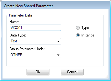
iii. To add any new parameters
that don’t exist, click the ‘New’ button in the tool.![]()
iv. This will bring up the ‘New’ parameter dialog where you can give it a name and data type.
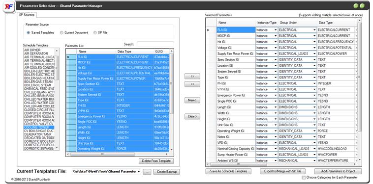
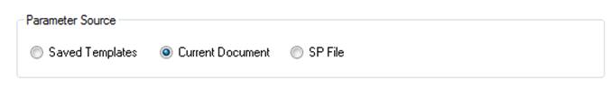
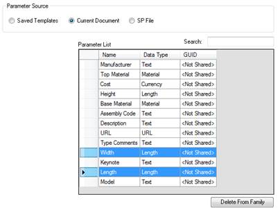
v. After creating your new parameters, you can add any existing project shared parameters to the list by selecting ‘Current Document’ from the parameter source selection. Assuming that the parameters ‘Fire Rating-1Hour’ and ‘Fire Rating-2Hour’ were already existing as shared parameters in the Architectural model, they would show up in this list.
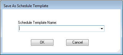
vi. Use the button ‘Save As Schedule Template’ and give it a name if you wish to reuse this list later. Otherwise, just click ‘Export to/Merge with SP File’ to create a new shared parameters file that you can then send to your project team.
![]()
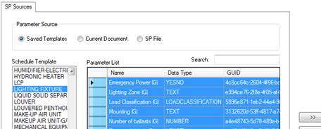
vii. When you receive a shared parameter file from someone, choose ‘SP File’ for the Parameter Source and browse to the received file.
viii. Add the desired parameters from the file to your current selection and click ‘Add Parameters to Project’ to have them available in your project.
![]()
ix. You have the option of assigning all the parameters to the same project element categories, or being prompted for project categories for each new parameter.
3. Replace existing family or shared parameters with new shared parameters
a. ‘Family Parameters’ cannot show up in schedules or tags, but you can convert existing family parameters to be shared parameters using this tool.
b. EXAMPLE: Make existing non-schedulable parameters schedulable:
i. Let’s assume you have a table family that has a length and width parameter, but they cannot appear in schedules and tags because they are not ‘shared’.
ii. Open the table family and select ‘current document’ as the parameter source to see the included parameters
c. 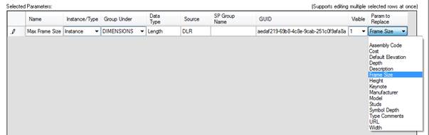
d. Add the desired parameters to your selection. They will automatically be converted to shared parameters and will automatically set their mapping to replace the existing parameters of the same name in the family. Replacing the existing parameters will maintain any existing formulas, defaults, label or dimension associations, etc.

e. Click ‘Add Parameters to Family’ to have them replaced in the family. They can now be used in schedules and tags. If you need to add these same parameters to a tag family, you will want to save this as a schedule template in the tool then select this saved template when editing the tag family.
f. EXAMPLE: Replace manufacturer provided parameters with your standard parameters:
i. Let’s assume that you downloaded a family from a content site or a manufacturers website and it has shared parameters, but they are not the same parameters that you are using to schedule this data.
ii. This is very similar to the previous example except that you will have to manually select which parameter to replace.
iii. With the family open, open the Parameter Scheduler and find your standard parameter by selecting the appropriate saved template or shared parameter file.
iv. Add it to your selection then find the column called ‘Param to Replace’ and select the existing parameter to replace.

v. Note: To replace a parameter, both parameters must have the same data type. If not, you will be notified that both parameters will remain in the family.
vi. Note: You can save the new template settings and the parameter replacement map settings will be saved for future use.
4. Add new shared parameters to current family or project with or without adding the parameter to your company shared parameter file:
a. Creating new shared parameters can be normally tedious and may involve creating a new file or saving to an existing standard shared parameter file that employees may not have write-access to.
b. Start by clicking the ‘New’
button in the tool.![]()
c. This will bring up the ‘New’ parameter dialog where you can give it a name and data type.
d. After creating your new parameters you can choose whether to add them straight to the family or project or to export them to a new or existing shared parameter file.
5. Saving Schedule Templates
a. Saving groups of parameters as a ‘schedule template’ is a convenient way to save lists of parameters, ‘group under’ settings, or replacement maps for further use.
b. Lists of parameters can come from multiple sources and can be a combination of existing templates, existing parameters in a project or family, and come from multiple shared parameters files.
c. After creating your custom list in the Selected Parameters list, you can click ‘Save As Schedule Template’ to be prompted for a template name.
d. You can update an existing template or create a new template name.
6. Other Notes
a. You can modify multiple rows simultaneously (for example, changing the ‘Group Under’ setting for multiple parameters) by selecting cells or rows of multiple parameter entries before making the edit.
PARAMETER LINKER
The Parameter Linker is used to allow users to link parameter values between any two elements, even if the element is in a linked file. This means that if the value in one element is updated, the value in the linked element will also update. Note that values will only be written in the current model and will not be written through links. Example: If a value in a linked model changes, then the current model will be updated to match, but not the other way around. You would have to open the linked model to manage parameter links in that model to write parameters in that model. The default update procedure is to open the Parameter Linker tool to manage the links and review any discrepancies, but automatic updating is also an option.
The parameter linker works on two sets of data.
1. A list of element pairs: This list defines which elements are linked and share information.
2. A list of parameter sets: These are lists of parameter pairs that define which parameters in a source element will transfer data to which parameters in the destination element. You can create as many named sets of parameter pairs as you want.
You create a complete link by assigning a parameter set to your pair of linked elements. This allows you to create common parameter sets that when modified will update all element pairs referencing that set. You can also import previously saved templates of parameter sets if desired.
If you are just linking two elements, you can either select them before opening the tool, or you specify them in the tool by element id or selecting them in the interface.
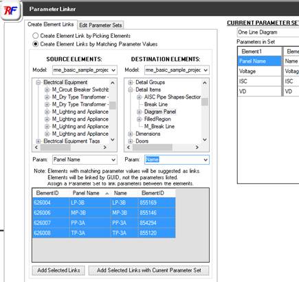
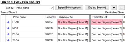
Alternatively, you can linked large sets of elements at once by selecting a parameter that has a matching value. For example, we know that the ‘Panel Name” parameter of our electrical equipment has a matching value in our diagram detail items' parameter ‘Name’.
So, we select the categories, families, or types that we want to match and we select the parameters that would contain matching values. Any elements having matching values are displayed and available for linking.
When linked, they are linked by unique ids and not this parameter value, so these parameter values can change and you can decide whether they are linked. You can accept the matches as linked pairs with or without assigning a parameter set at this time. If no parameter set is selected for a pair, no data will be linked between the elements.
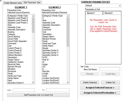
If you are setting up a project for the first time, you will need to create parameter sets to define which source parameter names are linked to parameter names in the destination elements. Parameter sets are unique to each project and can also be imported from other projects if you have previously set up templates. The source and destination parameter names do not have to be the same, and you can even link parameters of different data types (as long as they can be converted to each other).
With the ‘Edit Parameter Sets’ tab activated, you will see available parameters shown which are pulled from the selected element links in the links list at the right and any elements shown on the Create Element Links tab. Simply select a source and destination parameter and add them to your current set.
The Current Parameter Set shown is the one that will be applied to newly created element pairs. You can also apply it to existing element pairs. If the edited parameter set is already used by elements, all of those elements will already reference the changes you just made. You can change parameter set assignments and manage parameter set changes when this tab is visible. You have the option to apply the first column of parameter names to either the source or destination element pair, and you can always swap which element is the source in the links list if you want to push data the opposite direction.
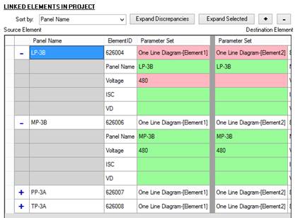
1. Manual review and updates
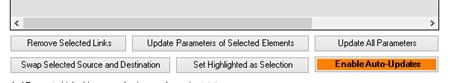
a. The default workflow for the program is to periodically open the Parameter Linker to manage any discrepancies. Any elements and parameters that have discrepancies will be highlighted red for your review. You have the option to update all linked pairs or just the selected ones. You also have the option to swap source and destination to push data the opposite direction. For example, if you just finished making changes to a diagram whose elements were set as the destination in the element pair, you could swap them to be the source so you could push data from the diagram to the floor plan instead of the other way around.
2. Automatic Synchronization of changes
a. Enabling automatic updates will automatically monitor all linked elements for changes while you are designing. Any changes to monitored elements will trigger a synchronization of all parameters in the parameter set assigned to those elements.
b. The element you modify will be treated as the source during the synchronization, so whether you edit the source or the destination element listed in the link list, the changes will synchronize to the linked element.
c. Note: Versions 2014 and earlier will only synchronize changes made to the source element in the list, so changes made to linked parameters in a destination element may be overwritten the next time the source element is modified.

3. Other features
a. The Sort by box allows you to specify a parameter name for listing the linked elements. This makes it easier to find the element and information you are looking for and compare its parameter values.
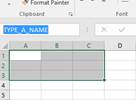
b. The Set Highlighted as Selection button allows you to highlight all the selected pairs in the Revit interface. This can be useful for quickly seeing which elements have or have not been linked and quickly locate elements for editing.
DRAFTXL
The DraftXL program is for getting formatted Excel tables into Revit so they can be part of your documentation. Tables such as load calculations, code compliance forms, or other reference schedules that are not based on Revit data but are still important to display in Revit can be read in using the DraftXL program and converted to Revit drafting views.

After selecting the Excel file you want, you have two options for determining the range to import.
1. Named Range(s): In Excel, you can name any selected range by just typing a name in the name box at the upper left. This is important if your range will grow in any way such as adding rows and columns. The named range will automatically keep track of rows and columns added.
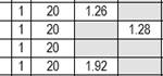
a. This method also allows you to select multiple named ranges so that you can import tables from multiple tabs in an excel file at once without having to do the import process separately for each one.
2. Specify Range: This allows you to specify any range based on its start and end column letters and row numbers.
The tool will keep a log of all tables brought into Revit for the current project and will store that data in a .txt file in the project folder. The save path is listed at the bottom of the tool and is selectable by the user. The user may also make manual changes to the text file, such as updating the Excel range or Revit view name, if desired.
The saved log at the right will indicate to the user whether or not the Excel file has been modified since the last time it was imported. When you choose update a file import, it will delete the drafting view previously created and recreate it from scratch using the saved settings.
The user can customize some of the ways the tool interprets the Excel graphics it reads. If the text or line sizes are not coming in as expected, you can adjust the scaling and such.
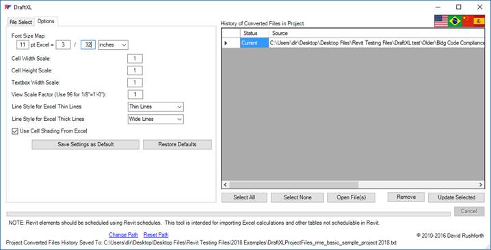
1. DEFAULTS AND OPTIONS:
a. FONTS: The tool reads the font type and styles from Excel and uses the same fonts in Revit. Changing a font name, size, underline, bold, etc. in Excel will change it in Revit as well. Fonts in Excel are measured in “points” and are converted to measurable dimensions such as inches or mm. You can change the Font Size Map in the options and all other font sizes will be scaled proportional to the base conversion.
b. CELL WIDTH AND HEIGHT: The cell width and height in Excel are based on “points” and on character spacing/widths for the current font. These are converted for Revit to be based on measurable dimensions such as inches or mm. The conversion should make tables appear in Revit the same as they appear in Excel, but there are some font types that will have slightly different results. Stretching the cell width or height in excel will stretch it in Revit as well. If you want to widen or heighten a cell scaling even further, set the cell width scale or the cell height scale in the options.
c. TEXT WRAPPING: The location at which text wrapping occurs in Excel and Revit are completely independent from each other. This is governed by the offsets and padding that each uses and changes for each font type. For that reason, there may me some slight differences in where that text wrapping occurs in each. If you want to stretch or contract the textbox in Revit to affect where that wrapping occurs, you can change the textbox width scale in the options.
d. CELL SHADING: The tool can create shaded regions for cells that are shaded in Excel. You may also turn this off in the options. Note that all colors of shading in Excel are converted to gray shading in Revit.
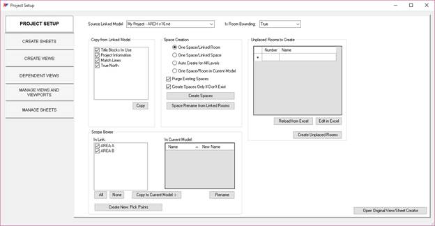
2. REPORTED ISSUE
a. A user has indicated that using computers with font scaling in the Windows display options may cause some of the default scaling of the imported tables to be affected. The tool works best when scaling is set to 100%. A future release of the tool will likely resolve any discrepancies caused by Windows scaling.
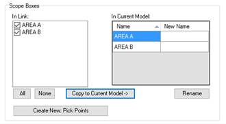
PROJECT SETUP (VIEW AND SHEET CREATOR)
The Project Setup tool is used to quickly copy project-wide elements like scope boxes from a linked model, batch create sheets and views from lists or templates, create dependent views, and manage the views and sheets throughout a project. There are many features in this tool that will save several days’ worth of work throughout the life of a project.
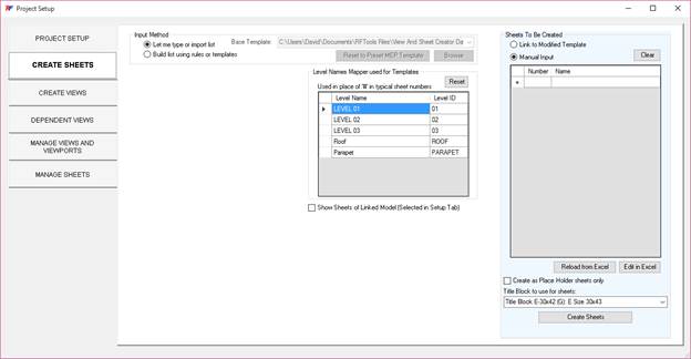
It is time consuming to open multiple models to transfer items between them and it is not always a straight forward task. This tab gives you access to common elements and settings that are shared between linked models.
1. Linked model selection
a. If there is only one linked model, then it will automatically be selected. If there are multiple linked models, then you must select which linked model you want the tool to reference.
b. This selection affects all tabs of the Project setup tool such as viewing the linked model views and sheets for reference or copying the linked model viewport locations.
c. You also have the ability to view and set whether the link is room bounding. If you will be creating spaces or rooms that you want to be bound by this link’s geometry, then this should be set to “True”.
2. Copy from linked model
a. All items checked will be transferred to your current model
b. Items include: Title blocks, project information, match lines, and true north
3. Space creation
a. You can automatically create MEP spaces throughout your entire project by copying rooms or spaces in a linked model, by generating them on each level based on geometry, or by copying rooms in the current model.
b. When copying rooms and spaces, important properties such as the names, numbers, and offset information are retained
c. If the rooms in the linked model are modified, you can choose to update the names and numbers in the current model to match the changes.
4. Scope Boxes
a. This feature allows you to see all the scope boxes in the linked model and the current model.
b. You can select which scope boxes in the linked model you would like to copy into the current model.
c. You also have the option to rename the scope boxes in the current model.
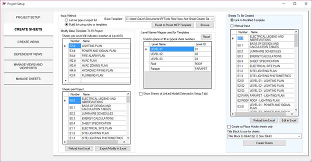
5. Unplaced Rooms to Create
a. This tool allows you to quickly create unplaced rooms for space planning purposes.
b. You can enter them directly, or you can use excel to import a list of unplaced rooms to create.
1. You can use the Create Sheets tab to set up multiple sheet names and numbers
2. Let's first assume you have a list of sheets in excel that you received from the project manager
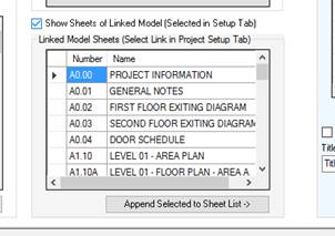
a. You can either just type the information in the table at the right, or click the “Edit in Excel” button to copy and paste the values in.
b. Once the Excel file is saved, just click “Reload from Excel” then click the create button.
3. The other option is to build a list based on the levels in your project
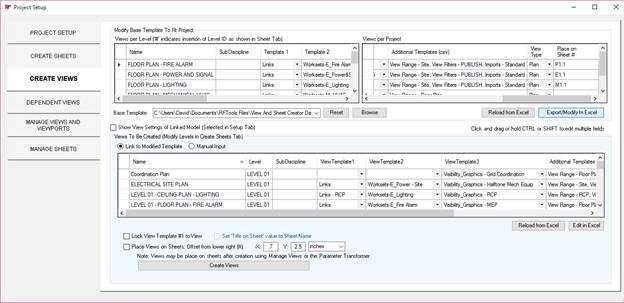
a. You can specify the sheets to create per level and per project.
b. The levels in the project are listed and you can choose to delete levels or change how they are numbered.
c. As you edit the lists of sheets per level or sheets per level, the list of sheets to create (at the right) is automatically updated.
d. The list at the right shows the sheets that will be created. You may edit the final list in the table or in excel before creating.
e. If you wish to save these settings as a template you can export them to an excel file. You can also use excel to make additional edits to your template.
f. The last few templates used are available in the drop down selector for quick access.
4. At any time, you can check the box to view the sheet numbers in the linked model so you can verify numbering and naming conventions.
a. You also have the option to append sheet numbers and names from the linked model to your model.
b. This can be an easy way to create place holder sheets based on linked models’ sheets.
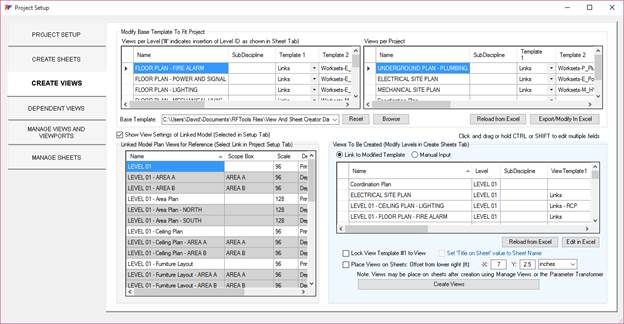
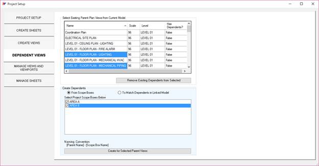
1. The create views tab works similarly to the create sheets tab in that you can edit lists in Excel or modify the templates to create your final view list from per-level and per-project lists
2. You may find it helpful to click on any one of the headers to sort the lists in order to easily apply various settings
3. You can apply any number of view templates to the views when creating or managing the views. The “Additional Templates (CSV)” column allows you to type any number of template names separated by a comma.
4. Again, you can show the linked view settings if you want to coordinate any settings or naming conventions
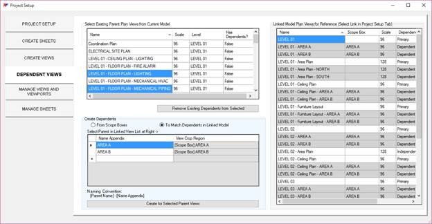
5. You can save these settings for future use in excel and edit the settings in excel as well.
a. The second tab in Excel contains the lists of views and sheets to create per project and per level. These can be applied to any project with any number of levels. The first tab of the excel file is where the tool temporarily stores the final lists to be created per the project and these lists get overwritten each time a new list is generated
6. When creating views, you have the option of locking a view template to the view. You also have the option to place the views on sheets. These functions can also be done later in the Manage Views tab.
1. Many projects will use dependent views to separate a floor plan into sections like halves or quadrants
2. To create dependent views for multiple views, you just select the primary views at the top and the desired scope boxes. Then just click to create the dependent views.
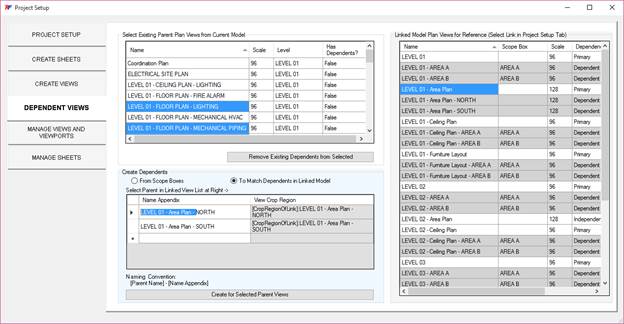
3. OR You can match whatever is being done in the linked model
a. In the screenshots below, you can see that the linked model is using scope boxes for most of their views and cropped regions for the area plans.
b. You can edit the default view name appendix that you want to show up at the end of your view names.
c. Any missing scope boxes or crop regions that don't exist will automatically be copied from the linked model.
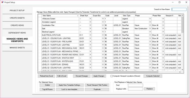
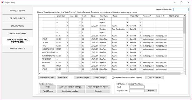
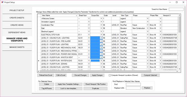
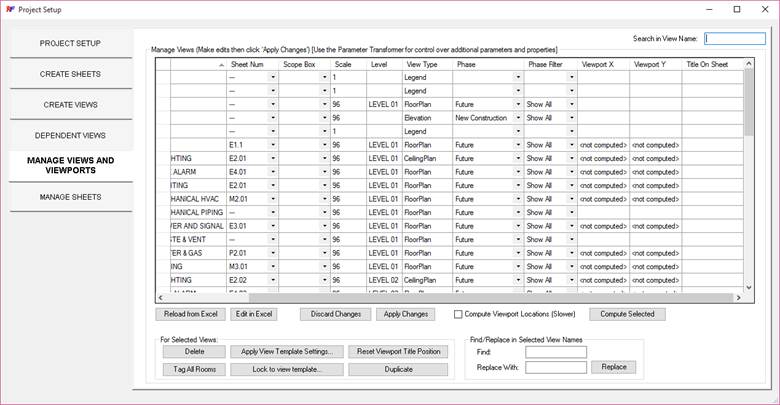
1. Throughout the life of your project, you may find it convenient to make bulk modifications to views.
2. You can use the search bar to filter view names as needed.
3. You can click and drag or use the CTRL and Shift keys to select multiple fields and modify all selected rows at once.
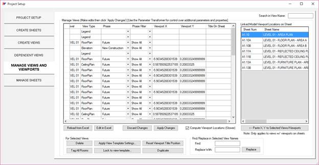
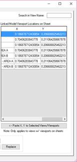
4. Using the fields at the bottom, you can find and replace parts of the view names
5. You can also place the views onto sheets by simply typing or selecting the sheet number.
6. All of these can also be edited in Excel for convenience.
7. You can check the box to compute viewport locations which will show you the coordinates where the viewports are currently placed and allow you to copy the positions from other views in the same model or from the linked model.
8. To use the viewport locations in a linked model, you can select the viewport in the linked model list then just copy that location to all desired views using a button. Note that setting viewport locations is a function that may take Revit a few minutes to perform depending on how many you are doing.
a. VIEWPORT PLACEMENT NOTES: The viewport X and Y locations are calculated based on the lower left on the sheet titleblock being 0,0. So, if you set the viewport X and Y to 0,0 then the bottom left of the viewport should match up with the bottom left of the sheet. There is a trick, however, in that the viewport position is based on the bounding box of the viewport. That means that the lower left of the viewport can be affected by grids, annotations, sections, etc. that extend beyond the border of the view. If these annotation objects are affecting viewport placement, you can turn off annotations in the views before aligning them, then turn annotations back on. If you are just setting up a project, and there aren’t annotations, but just grid lines, then you can just change the grids to an invisible workset temporarily then turn them back on after setting the coordinates. Some of this may be automated in the future.
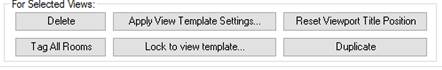
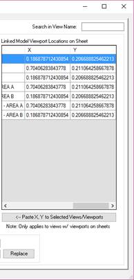
9. In this tab, there are also buttons to quickly perform other functions such as applying multiple view templates to multiple views, locking view templates, deleting, or even duplicating multiple views. There is also a tool to tag all rooms in selected views.
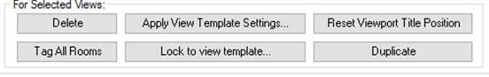
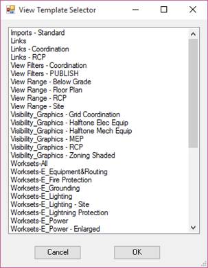
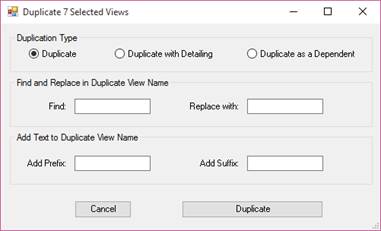
10. After changing scope boxes of views that are already on sheets, it may also be convenient to reset the viewport title positions to keep them aligned to the viewports.
11. For control over additional parameters and properties using excel, remember that you can always use the Parameter transformer tool on the toolbar as well.
1. The manage sheets tab allows you to similarly control common sheet properties in the interface or in Excel.
2. This tab also allows you to select a revision in the project and see all sheets that are affected by the revision. You can also apply the revision to all selected sheets so the revision information is displayed on the titleblock.
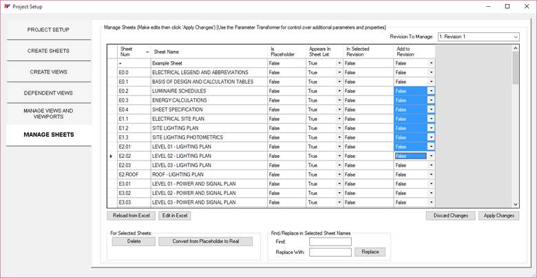
PROJECT FOLDER
Click this button to quickly open a windows explorer window in the central file location.
RAYTRACE MOVE DOWN
1. Select any number of elements that you would like to have move down to the nearest surface.
2. Click this button to display a list of the loaded models (including linked models).
a. 
3. Select from the list the model that contains the geometry to use for raytracing.
4. The elements will move vertically to the nearest surface. They will not move if no surfaces are found.
NOTE: Elements having constraints on them by a host or reference plane may or may not move depending on their constraints. If your elements do not move, then try different elements or try modifying the element in the family editor to remove any constraints that may be affecting its movement. Some family creation templates respond differently to the API trying to move them.
RAYTRACE MOVE CLOSEST WALL
1. Select any number of elements that you would like to have move to the nearest wall.
2. Click this button to display a list of the loaded models (including linked models).
a.
3. Select from the list the model that contains the geometry to use for raytracing.
4. The elements will move to the nearest wall.
NOTE: Elements having constraints on them by a host or reference plane may or may not move depending on their constraints. If your elements do not move, then try different elements or try modifying the element in the family editor to remove any constraints that may be affecting its movement. Some family creation templates respond differently to the API trying to move them.
RAYTRACE ELEMENT COPY: WINDOWS
This is a tool that is primarily used by energy modelers that at times find it convenient to approximate geometries contained in an architectural model. After approximating wall locations, energy modelers may replace the architect’s windows with custom windows that have appropriate parameters and information for energy modeling purposes.
1. Have walls modeled in the current model that are approximately located near walls containing windows in a linked model.
2. Click the button to start the tool.
a. 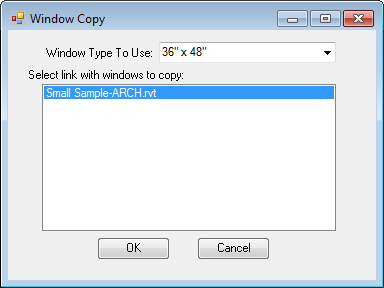
3. Select the window type of a loaded window that you would like to create at locations matching the existing linked model locations.
4. Select the linked model to copy windows from.
5. Click OK to copy the length and width information as well as the window locations from the linked model and find the closest walls in the current model to copy the windows to.
OPEN CAD LINK
1. In a Revit view, select the line work of a linked CAD DWG file.
2. Start this tool to open the linked DWG file in AutoCAD for editing.
REMOVE FROM CIRCUIT
1. Select multiple elements that are connected to electrical circuit systems.
2. Click this button to remove all of the selected elements from their respective circuits without having to edit each circuit individually.
NOTE: If the removed element is still connected to other elements by Revit wires, the connected elements may be affected when re-circuiting the disconnected element.
MERGE/MOVE CIRCUITS
1. Select multiple elements that are connected to multiple circuits
2. Start the tool
a. 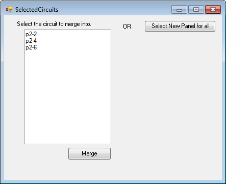
3. Choose one of the selected circuits and use the ‘Merge’ button to move all of the selected elements to the selected circuit.
4. OR Choose ‘Select New Panel for all’ to move all the indicated circuits and all their associated elements to a new panel.
SPARE RATING/RENAME
1. Start the tool
2. You are given the option to affect all breakers named “Spare” or only those that haven’t been assigned a breaker rating yet.
a. 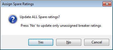
3. Click ‘Yes’ or ‘No’ to change the text of spare breakers to upper case and set the default of all unassigned (and optionally assigned) breaker ratings to 20 A.
CREATE HOME RUNS
1. Click this button to create a home run for each circuit on the sheet.
2. It creates the home run on the closest element to the feeding panel.
FREE MOVE
1. Select any number of elements.
2. Start the tool and follow the instructions in the lower-left notification area that indicate to choose a start position and end position for moving the elements.
3. This tool is similar to moving elements using the disjoin command, but unlike the disjoin command, it will not erase your system connections and circuiting.
NOTE: Elements having constraints on them by a host or reference plane may or may not move depending on their constraints. If your elements do not move, then try different elements or try modifying the element in the family editor to remove any constraints that may be affecting its movement. Some family creation templates respond differently to the API trying to move them.
TAG LIGHT FIXTURE
1. Select multiple light fixtures, or start the tool with none selected to tag one by one.
2. Select the button for the types of tags to create.
3. This tool will place tags on all selected lighting fixtures (or you can select the fixtures one by one) and will automatically place and adjust the and orientation of the tags based on fixture placement and orientation.
NOTE: Proper placement depends on the tool finding parameters named Length, Width, and/or Radius
ELECTRICAL FIXTURE CIRCUIT TAGGER
1. Select multiple electrical fixtures.
2. Start the tool
a. 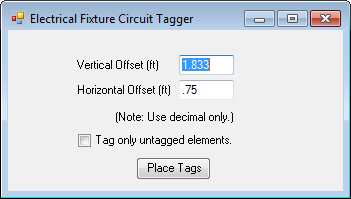
3. The default spacing is approximate for an electrical receptacle. Adjustments can be made for tagging electrical fixtures of various sizes.
4. Click ‘Place Tags’ to tag all the selected devices with their circuit number. If desired, you can select all instances of the created tag and change the type to a different tag.
SPACE AND ZONE TOOLS
1. Start the tool.
a. 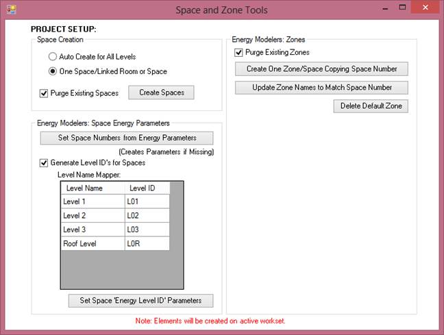
2. Choose whether to automatically place spaces in all found void spaces in the model or whether to create spaces from a linked model’s rooms or spaces
3. Click ‘Create Spaces’. If you selected to create spaces from a linked model, a new dialog will appear.
a. 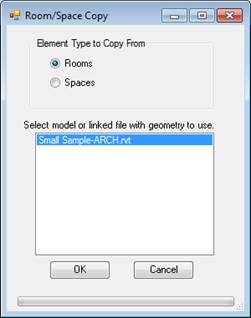
b. Choose rooms if creating spaces to match rooms in the linked model and choose spaces if creating spaces to match spaces in the linked model.
4. After selecting the linked model to copy from, press ‘OK’ to create spaces in the same location and with the same parameters as the elements in the linked model. Note that only a number of compatible parameters will be copied when translating from rooms to spaces. These include, of course, the room name, number, and height.
For energy modelers:
The Zone portion of this tool will create one zone per space for use in exporting to certain analysis applications. It creates three parameters “Energy Level ID”, “Energy Zone Type”, and “Energy Order Number” that can be concatenated to the space number parameter for exporting to Trane Trace. The Space number gets copied to the zone name for exporting to other energy modeling tools. The Parameter Transformer can be used to facilitate populating these parameters with meaningful data.